
Group 1160
Solidification of eutectic alloys under microgravity
Detailed Experimental Description
Experimental objectives
The experiment group:
Erkki Anttila
Mikko Suominen
Juha Tuisku
Kimmo Vänni
Endorsing Professor:
Professor Toivo Lepistö
Supervisor:
Professor Veli-Tapani Kuokkala
Our preliminary results can be found here.
Experimental objectives
The aim of our experiment is to produce samples of eutectic and other alloys under microgravity conditions and later to investigate the differences in materials that are solidificated under microgravity to the ones solidificated on the ground.
The characteristics and effects that we are going to compare are the microstructure, especially the distribution of the two phases, and the resulting properties of the produced materials. This analysis is going to take place at Tampere University of Technology after the experiment.
Detailed Experimental Description
Equipment used
- samples of two eutectic alloys, conventional PbSn and lead-free SnAgCu solders
- apparatus consisting of a box-like arrangement which is compact and easy to attach to the attachment rails. The box is a metal one with no sharp edges. One side of the box is open for the operation of the equipment. During the heating, this side is covered with a fireproof plexiglass for safety reasons.
Numerical data of the equipment:
Dimensions: 340 mm (width) x 240 mm (length) x 315 mm (height)
Mass: 20 kg
Centre of mass placement: roughly in the middle of the box
Current taken: maximum 1 A at 230 V (fused with 1 A)
We changed the original power source that didn’t stand out the high current and low voltage to a better current source that is built from components that easily stand the required current. We also have added a small air compressor to cool down the samples. It is controlled from a switch that chooses between the heating (heating current) and cooling (compressor). Also there is a main power switch and the emergency shutdown switch.
1) Inside the box we have our power source that operates with 230 volts provided in the aircraft. It will give high enough current to heat up the samples. The voltage is very low. The current taken from the airplane’s power source will be less than 1 A.
2) The samples (2 at a time) are placed in the fuse holders. The samples are fuse-like, where in the middle goes a wire that is heated by the current that comes from the power source. The wire heats the sample which, after a few tens of seconds, melts. The sample is inside a fuse-glass so that no drops of liquid alloy can get out. The fuse holders are attached to a steel bar which, in turn, is fixed to metal supports attached to the side panels of the box. The melting of the samples is observed with a magnifying glass attached to the plastic cover of the box. With it the surface of the sample and the melting of it can be observed.
Photo 1: The box from above. The hinged plexiglass and the magnet holder are still missing from this picture. Some badding to the edges and corners of the box will also be added.
In the upper left corner of the power supply is an ammeter to show how much current is going through the samples. We have tested that 15 A is enough to heat the sample to the melting point in less than one minute (the maximum current that can be drawn from the power supply is about 30 A). Under the ammeter is the main power switch and on its right side a lamp indicating the power on/off. In the middle is the current adjuster. The emergency power off switch is the big red button in the upper right corner of the power supply. The black switch in the right chooses between heating (heating current) and cooling (12 V DC to the air compressor). The current source is protected from touching with an aluminum plate on its bottom side (see the photo). The compressor can be seen on the bottom of the box. The two samples are placed in the fuse holders mounted on the rail (in the picture, only one sample is attached). Samples are changeable from the opening upper side (see the photo) of the box. The steel bars seen in Photo 1 below the box are for fixing the box in the airplane rails.
Photo 2: The box from the side
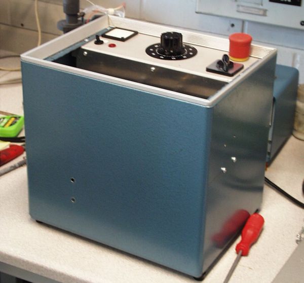
Photo 3: Sample tube
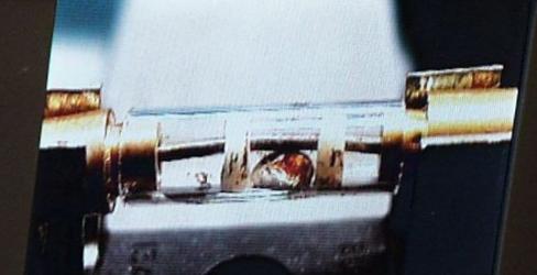
Photo 3 is a zoomed picture of the sample tube which is about 4 cm long. The tube is placed in the fuse holders attached the metal bar. In both ends of the sample tube there are metal parts that clip into the holder. Between them there is a fuse glass (good heat durability). In the middle goes a low resistance wire that is heated up by the current. The sample alloy itself is between two ceramic discs which prevent it from moving sideways. The melting of the sample can be easily seen with a magnifying glass attached on the plexiglass lid of the apparatus (also made of plastic for safety reasons).
Figure showing the current source circuit diagram. The Emergency button is placed in series with the power in so that it takes all voltage off from the equipment when it is pushed. The button size is about 30 mm in diameter and 30 mm in height.
Theory
In so-called eutectic solidification a homogeneous melt decomposes at a certain temperature into two solids. For Pb-Sn (38%-62%), for example, this temperature is only 183 °C, which makes experiments with this alloy easy. SnAgCu (95.8%-3.5%-0.7%) is a lead-free solder with a melting temperature of 221 °C. In normal gravity buoyancy-driven convection disturbs the process of solidification and in microgravity the almost complete lack of this effect will produce a different kind of structure compared to the ones produced under gravity. The properties of electronic materials are directly related to the chemical and crystalline perfection of the material. However, perfect crystals are not normally the ultimate goal. The presence of just a few intentional impurities in some eletronic materials can drastically affect their ability to conduct electricity. Alloys with particular kind of impurities are also included in our samples.
Procedure
The experiment works as follows: the sample is heated up by the wire (that heats up by the current flowing through it) enough to get it liquefied before the microgravity time. The amount of superheating (i.e., the temperature of the liquid) is controlled by the heating current. When the heating current is turned off, the sample solidifies during microgravity either unaided or with the help of compressed air. After the jump, the tubes containing treated samples are changed to new ones with samples for the next experiment.
Also the effect of magnetic field to the solidification of the sample will be tested by placing a strong permanent magnet adjacent to the specimen. The magnet will be attached firmly to an adjustable metal slider fixed on the same metals bar as the fuse holders.
We plan to make the experiment as simple as possible for the time in the flight so that the only thing we have to do is to push the button and see that the apparatus works properly and to change the sample tubes between the parabola jumps. Manual control will also be available, even if the process should be able to be executed automatically by logic.
The greatest difficulties that we can imagine in our experiment are:
1) Cooling: Our sample has to be small enough to get it solidified thoroughly in the short time of microgravity.
2) Timing: The sample should also be as long as possible in liquid state under the microgravity to assure that the compounds will be mixed in optimised way.
At least the cooling problem should be solvable on the ground. Placement of a surface (e.g. copper), which the sample rests on, would conduct heat away from the sample. A liquid cooler on the other side of this surface would enlarge the cooling effect. The cooling rate can affect the structure in the sample and therefore we want to make the cooling as smooth as possible. The sample does not have to be large for us to be able to analyse it later (only 5 mm x 5 mm x 5 mm should be enough).
The timing should also be reachable because we can make the experiment multiple times on both flights. With help of the gravity probe and the thermometer we could make exact observations of the conditions to be used later when the analysis of the samples is made.
We could also try to produce some samples during the phase of the flight when the gravity is greater than normally, just before or after the jump.
Also the effect of minor electric or magnetic field to the sample could be tested if we have got enough time. Also other changes in the conditions could be arranged and their effects would be later compared to effects resulted from similar conditions on the ground.
Analysis of samples on the ground
The effects in the samples that we want to investigate are:
-Eutectic distribution in samples
-Crystalline structure
-Impurity distribution in samples
-Electrical conductivity
-Thermal conductivity
Eutectic distribution (evenly dispersed, multiphase structure) is the most important one of the effects, because buoyancy-driven convection that affects the distribution of the alloy components should be very small in microgravity. We expect to accomplish a uniform matrix-structure where the component with greater volume ratio forms a matrix-like framing where the other component is uniformly divided into alike pieces.
Using some minor impurities in the some of the samples will also give us chance to investigate their distribution and how that differs from the samples made on ground. The microstructures will be sudied and analyzed using scanning electron microscopy (SEM), transmission electron microscopy (TEM) and energy dispersive spectroscopy (EDS). Electrical conductivity in these samples would also be examined.
The equipment needed for these kind of analysis is provided by Tampere University of Technology